In Ethernet networks, some messages are meant for every device on the local network.
These are called broadcast frames, messages that tell all nodes, “listen to me.”But how far can such a broadcast actually travel?
That depends on the broadcast domain, the logical portion of the network where a broadcast frame can reach every other device.How Far Can a Broadcast Travel?
Think of it as the “shouting range” of your network; everyone within that area hears the same message.
Let’s take a simple example to visualize it.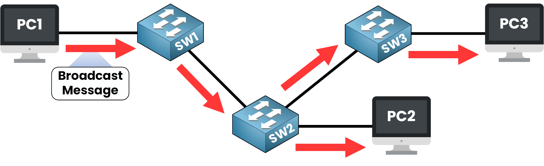
Figure 1 – PC1 broadcasts an ARP request to all devices
PC1 sends an ARP request, a broadcast message used to discover another host’s MAC address.
The frame is sent with the destination MAC addressFF:FF:FF:FF:FF:FF, which literally means “to all devices on this LAN.”Since only switches are involved, each one forwards the frame out of all ports except the one it came from.
This behavior is part of how Layer 2 devices handle broadcast traffic inside a network segment.
As a result, the message reaches every connected device, even those located behind other switches.
All these devices share the same broadcast domain, a single Layer 2 boundary where broadcast traffic can flow freely.Answer the question below
Switches operate at Layer 2 and do not create boundaries for broadcast traffic.
When a broadcast enters one port, the switch simply copies it to every other active port.That’s how a single switch can reach every device within its network segment.
But what happens when you link multiple switches together?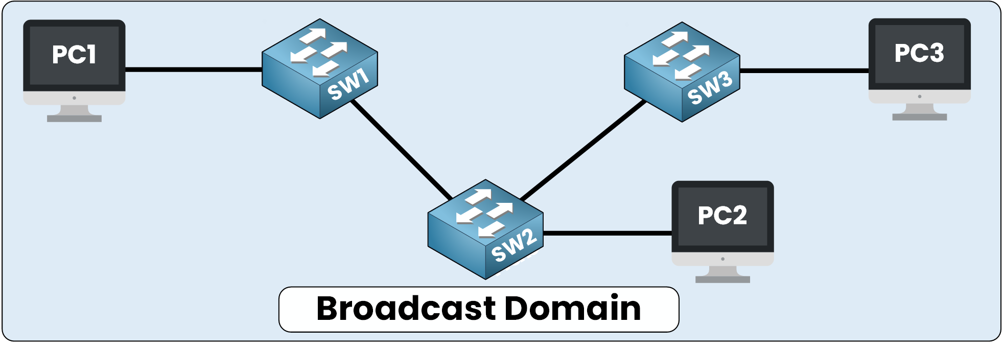
Figure 2 – Switches extend the broadcast domain across the entire network
Each switch repeats the same behavior, forwarding broadcast frames to all connected ports except the one they came from.
The result is that the broadcast keeps traveling, hop by hop, across the entire switch network.The Downside of Large Broadcast Domains
It’s simple and efficient for small LANs.
But as networks grow, this behavior becomes a double-edged sword.Every broadcast frame consumes bandwidth and processing power, even on devices that don’t need the message.
Over time, this flood of unnecessary traffic leads to broadcast overhead and reduced performance.That’s why large networks must be segmented.
Without boundaries, one broadcast can reach hundreds of devices and slow all of them down.Answer the question below
Can switches stop broadcast traffic from spreading?
Unlike switches, routers are designed to stop broadcast traffic.
They act as natural boundaries between networks, ensuring that broadcast frames never spread beyond their intended segment.Routers operate at Layer 3 of the OSI model, where forwarding decisions are made using IP addresses rather than MAC addresses.
Why Routers Do Not Forward Broadcasts
Whenever a broadcast frame reaches a router interface, the router processes it locally but never forwards it to another interface.
This is because routers operate at Layer 3 and make forwarding decisions based on IP addresses.
Layer 2 broadcasts are not routed between subnets.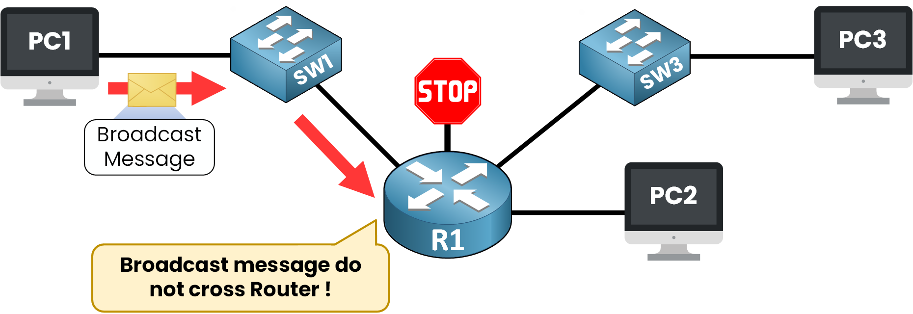
Figure 3 – Routers isolate broadcast domains by default
We can confirm this by looking at the router’s active interfaces:
R1# show ip interface brief

Interface              IP-Address      OK? Method Status                Protocol
GigabitEthernet0/0     192.168.1.1     YES manual up                    up
GigabitEthernet0/1     192.168.2.1     YES manual up                    up
GigabitEthernet0/2     192.168.3.1     YES manual up                    up
This output shows that R1 has three active interfaces, each configured in a different IP subnet:
192.168.1.0/24
192.168.2.0/24
192.168.3.0/24
Each interface represents a separate broadcast domain.
Now imagine PC1 sending a broadcast frame within the 192.168.1.0/24 network.When the frame reaches R1 on GigabitEthernet0/0, the router recognizes it as a Layer 2 broadcast.
Instead of forwarding it to GigabitEthernet0/1 or GigabitEthernet0/2, the router stops it.Devices located on other networks, such as PC2 or PC3, never receive that broadcast.
This behavior defines the router’s role as a broadcast boundary.In other words:
Each router interface marks the edge of a separate broadcast domain.
Because of this, each subnet operates independently, preventing broadcast traffic from spreading across the entire network.
Answer the question below
Which device stops broadcasts from spreading to other networks?
Now that you understand how routers block broadcast traffic, let’s look at the bigger picture.
In a network with multiple interfaces, each router interface automatically creates a distinct broadcast domain.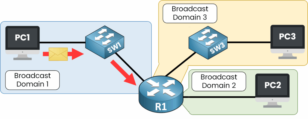
Figure 4 – Each router interface forms a separate broadcast domain
For example, if a router connects to three different LANs, each of those LANs becomes its own broadcast domain.
A broadcast sent on one network stays confined there; it never crosses over to another.Why This Segmentation Matters
Even though all devices might be physically connected through switches, the router ensures logical isolation between networks.
This segmentation reduces unnecessary broadcast traffic, prevents congestion, and keeps communication efficient and predictable.In short, routers don’t just route packets, they define boundaries that protect each network from the noise of its neighbors.
This concept forms the foundation of network segmentation and prepares you for understanding how VLANs achieve the same effect, but at the switch level.Answer the question below
How many broadcast domains does a router with 3 interfaces create?
So far, we’ve seen that routers naturally break broadcast domains by design.
But did you know that switches can do it too?That’s where VLANs (Virtual LANs) come in.
How VLANs Create Separate Broadcast Domains
A VLAN allows you to logically divide a single physical switch into multiple virtual broadcast domains.
Each VLAN acts as its own independent network, even though all devices are physically connected to the same switch.In the example above:
PC1 and PC2 belong to VLAN 1
PC3 and PC4 belong to VLAN 2
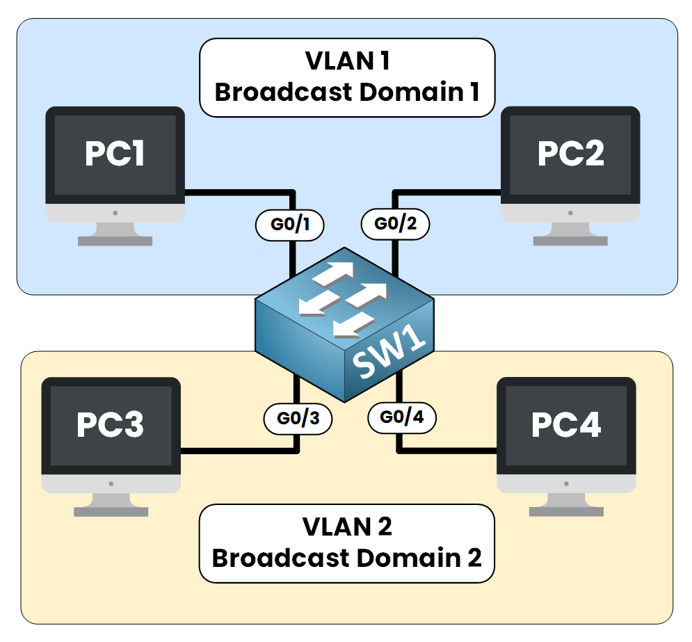
Figure 5 – VLANs separate broadcast domains on a single switch
Although all devices are connected to the same physical switch (SW1), the broadcast traffic from VLAN 1 never reaches VLAN 2, and vice versa.
We can verify this directly on the switch.
SW1# show vlan brief

VLAN Name                             Status    Ports
---- -------------------------------- --------- -------------------------------
1    default                          active    Gi0/1, Gi0/2
2    VLAN2                            active    Gi0/3, Gi0/4
1002 fddi-default                     active
1003 token-ring-default               active
1004 fddinet-default                  active
1005 trnet-default                    active
This output shows that:
Ports Gi0/1 and Gi0/2 belong to VLAN 1
Ports Gi0/3 and Gi0/4 belong to VLAN 2
Each VLAN represents a separate broadcast domain.
Even though all ports are part of the same physical switch, broadcasts sent from a device in VLAN 1 are only forwarded to ports within VLAN 1.
They are never sent to VLAN 2.
In other words:VLANs create logical broadcast boundaries inside a single switch.
Answer the question below
What allows a switch to have multiple broadcast domains?